We’ve controlled lights, checked our mail, connected our doorbell, and wired our smoke detectors, so let’s take a look at another device to connect to our Insteon system: the Insteon garage door control and status kit.
Really, this device is just an Insteon I/O Linc, which we’ve already covered before, with some wire and a magnetic contact closure similar to the one found in the TriggerLinc; it just all comes bundled in one package.
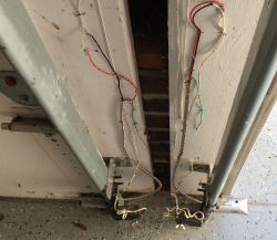
Setting this up is pretty straight-forward: the idea is you put the magnet on the door (I put mine inside the weatherstripping on the bottom) and secure the sensor where it will come in contact with the magnet when the door is closed.

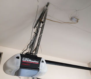
Next you’ll run the wiring up the wall to the outlet that the garage door is plugged into.
There you’ll plug in the I/O Linc with the sensor wires going into the input, and the control wires from the output going into the garage door’s input (check your garage door manual for this wiring; most garage doors will have this input and may already have the control buttons from the wall wired to it).
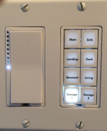
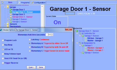
Next, add the IOLinc to your ISY-994i like you would any device. For each IOLinc you’ll see two items – one for the input and one for the output. You’ll now want your KeypadLinc buttons to light up when the door is open, but have the button itself toggle the door up or down:
.. and that’s the (slightly) tricky part. The first thing you’ll want to do is configure the IOLinc options for “Momentary A” with a small hold time. This tells the IOLinc to “close the circuit” when an on or off signal is sent to the output, but release it after a short period of time. Think of it as the same thing when you push the existing garage door button in the garage: you push the button, then let it go after a second, and the door reacts (closing if its open, and vice-versa). So if you want to know the state of the door, you look at the “sensor”, but if you want to control the door, you toggle the “output”. But this isn’t how you want to deal with it – you want those KeypadLinc buttons to handle the work for you. The trick to setting this up is the following:
- Create a scene in the ISY994i for each garage door named “Garage Door 1” and “Garage Door 2”
- Add the KeypadLinc button for each door to the respective scenes as controllers. You can add more than one button from different KeypadLincs in the house if you want (say, one in the kitchen and one in the bedroom).
- Add the IOLinc sensor to the scene as a controller. This will allow the light on the button to turn on and off based on the state of the door.
- Add the IOLinc output to the scene as a responder. This will allow that momentary signal to be sent to the garage door when the scene state is toggled.
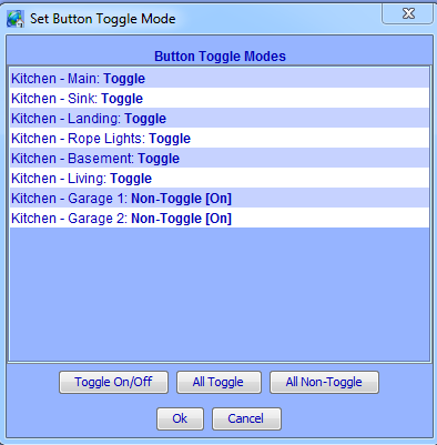
- Click on the KeypadLinc and click “Buttons Toggle Mode”. Here’s you’ll want to change the button mode to “Non-Toggle”. This ensures that clicking the button doesn’t turn the light “on” or “off” – remember, that’s what the IOLinc sensor is going to handle.
The net result of this is that when you push the button, the scene actually changes state. This change in state of the scene causes the IOLinc output to momentarily “latch”, making the garage door change state. When the door finishes doing what it’s doing, the sensor’s state changes, which again changes the state of the scene, which causes the button to either light up (if open) or turn off (if closed).


But the Enforcer contact switch is not part of the kit, right? Are you using that, or is that a legacy piece?
Max,
Yes, the picture of the “enforcer” contact pad is from an older version of this kit, but the new version of the kit does have a contact switch included. Contact switches are very simple two-part devices – one side has a tube inside it with two light pieces of metal (with a wire going to each side), and a magnet. Bring them together, the magnet pulls the metal together, and the circuit is closed, activating the I/O Linc.
The point: pretty much any contact switch will work for this application.
I have the garage kit purchased through SmartHome which included the SECO-LARM SM-226L-3 Magnetic Garage Door Contact Switch. This switch has three wires coming out of it a black, red and green. The kit that came from SmartHome does not explain what wire color goes into the I/O link and into what slot. Do you know?
Ryan,
That is odd; I haven’t seen 3 wires in a magnetic sensor like that. Perhaps one is “normally open” (no) and one “normally closed” (nc), as seen on some mechanical switches. That is, when the magnet is close to the sensor, the circuit for one pair of wires opens, and the other closes.
Either way, you should only need two, and the circuit should be “open” if the magnet isn’t close to the sensor, and “closed” when it is. These two wires will go in GND and SENSE on the I/O Linc – it doesn’t matter which (http://www.smarthome.com/manuals/2450qs.pdf). If you have a multimeter handy switch it to “continuity check” and touch various combinations of the three wires. If the multimeter beeps when the magnet is close to the sensor but doesn’t when you move it away, you’ve found your two wires. Alternatively you could use a flashlight bulb and a small battery like a AAA – if the bulb lights when the magnet is close and goes off when it move away then you’ve found your wires.
Hope this helps!
Great write up! This is the only version of controlling a garage out there that seems to be a) simple and b) works.
The only thing to add, is when linking the IOLinc to the ISY, the user must make sure the physical sensor is either not wired in yet, or “open” and wired to the normally open [N/O] wiring screw on the IOLinc, otherwise the KPL light will be “On” when the door is closed, and “Off” when the door is open.
I do see some strangeness with a “Query All” not reporting the correct state of the sensor (at 3 am) and turning on my warning indicators that one or both of the garage doors are open, when in fact they are both closed. Manually re-querying the IOLincs from the ISY console seems to resolve it.. Strange in that from the time we close ours eyes, till the time we open them, there is 0 household activity other than the 3am “query all”. This is the same behavior when using the UD programming “suggestions” on the wiki.
Well done, Matt!
Good points, thanks Eric! I too have occasionally seen gremlins in the system where the light occasionally doesn’t reflect the correct state, but for the most part I’ve been happy with the system setup.