The MakerBot 3D Printer is a pretty cool piece of technology that we’ve covered before. 3D printing technology continues to advance, as seen in this excellent infographic on ComputerScienceHub.org. While it still has a long way to go before we’re all printing our own cell phones at home, designing and printing plastic 3D parts is well within reach.
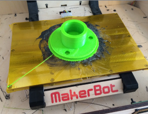
Thingiverse is a site that allows anyone to download ready-made 3D models for printing (I’ve put some of my own up there and written about them here), but today we’re going to talk about the steps to actually design your own parts. Specifically, a neighbor recently had a part break on his snow-blower and asked if I could print a replacement part.

The results speak for themselves, but not without caveat: unfortunately this part isn’t quite as strong as the original and has cracked a few times. I’ve evolved the design (using chamfered edges) and printing method (more plastic in-fill) over time, but this post is more about the design of the part itself.
Regardless of object you’re attempting to create, the basic steps are pretty much the same: select your software, build your shapes, and print. I’ve tried a bunch of different modeling software but the one I like most is AutoDesk’s 123D Design, which is free and powerful enough for most basic tasks. And, of course, we’ve already covered the printing stage. So, let’s look at the steps for building this part.
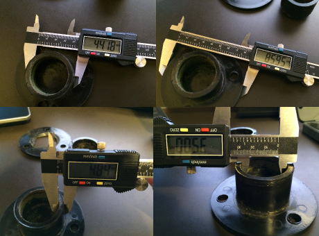
Measure the source part
Getting the dimensions right is important, and using an inexpensive digital caliper is key to getting some pretty precise measurements. For my part, I needed a handful of dimensions: the thickness of the base, the size of the hole, the height of the base and mount, and the size of the screw holes.
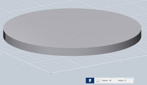
Build the shell
Most of what you’ll be doing in your modeling software will be creating primitive shapes such as squares, rectangles, and cylinders, then joining or subtracting them together to create more complex parts. Here, we start with a simple cylinder with a radius of 43mm and height of 6mm:
To that we add another cylinder with a radius of 22.5mm and height of 28mm:
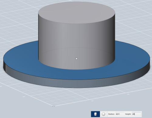
At this point we have two separate shapes created, and in order to create our single shell shape, we select both items and join them together to create one. We now have our basic shell with the right dimensions, but we’re going to need that mount hole and screw holes as well.
Subtract parts of the object
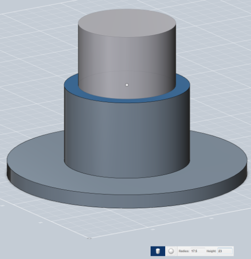
Notice that we didn’t put a hollow tube on top of the base, but a solid cylinder. In order to make a tube, we’ll create another cylinder and place it on top of the first. Its radius is 17.5mm and height is 23mm – just enough to leave 5mm around the edges and at the bottom.
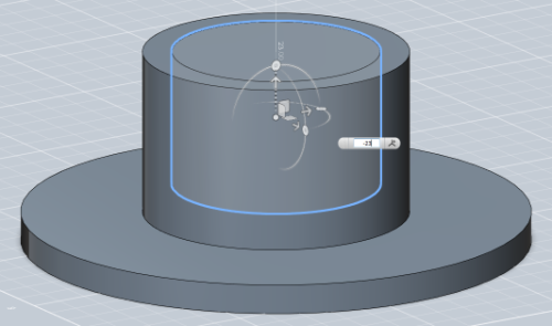
Because the height of this new cylinder is 23mm, we’ll now move it down “into” the other one by 23mm so that the tops of both are completely flush.
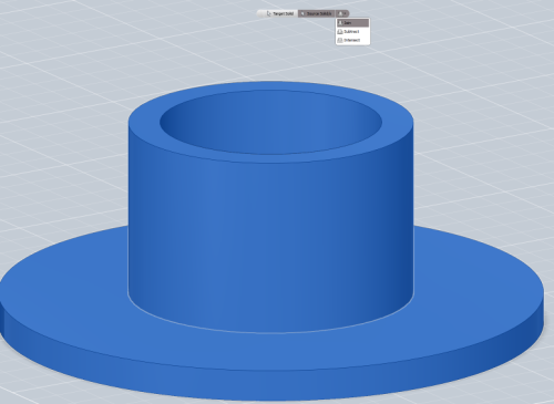
Now we want to “subtract” one object from the other, so we’ll select the shell and the inner cylinder and do that subtraction to get us the hole of the dimensions we want.
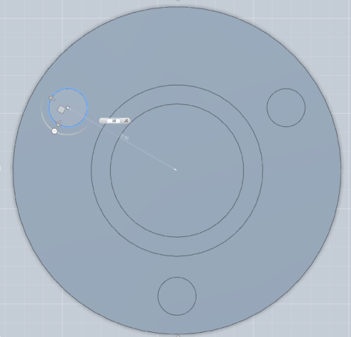
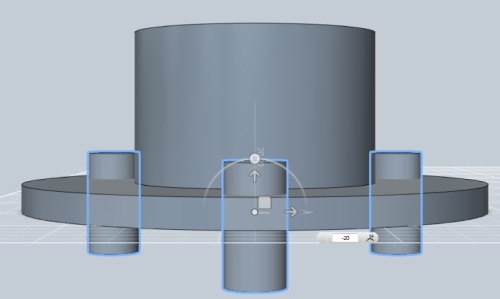
The 3 screw holes are done in a similar way by creating 5mm cylinders, pushing them through the base, and subtracting them, but there’s a problem: how do you place them equally around the circle without just “freehanding” it? The answer is to place them in a known position, and move them in a calculated way. In our case, it’s easy to place the cylinder snapped directly in the center, then we rotate the cylinder from above (which is a bit counter-intuitive since it’s a circle and looks the same at any rotation) in 120-degree increments. Knowing the radius of the circle and the radius of our new cylinders, we see that each needs to go 23mm off-center.
Push them through the base by moving them down:
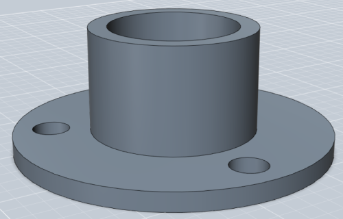
… do another subtraction, and your part is good to go:
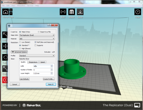
All that’s left is exporting the design to an .stl file, importing into your printing software, and sending that model to the printer:


Nice intro. Personally I’ve found OpenSCAD to be a much more powerful alternative to Autodesk 123D for anything that needs to be precise. Obviously as you demonstrated you can do precision with Autodesk 123D, but OpenSCAD lets you use a programmatic interface to generate your models. Downside of it, is there is a bit steeper learning curve (its basically a programming language), but syntax is just a google search away.