We’ve shown how installing an Insteon Switch is really straight-forward: turn off power, remove old switch, connect Insteon switch to the same terminals, restore power. It’s easy to do and doesn’t involve any wiring changes at all.
Multi-way switches (also known as “three-way” or “four-way” switches) are those that allow you to control a single light with more than one physical switch. These aren’t quite as simple to install, and actually require a subtle change to the wiring. Don’t worry; you’re not going to have to go ripping up walls or anything, but it’s important to understand how these switches work. Wikipedia, of course, has an excellent image demonstrating how most three-way switches work using what’s called a “traveler system”:
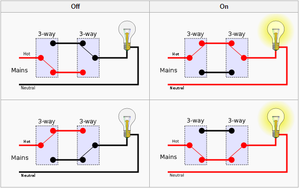
Look closely at the two switches above, and think about the problem: if you’re installing Insteon switches in both locations, which wire do you connect to “line” for the switch on the right? Because the left switch can be in either position, the wires coming into the right switch alternate where the current is coming in. Those two wires in the middle are actually called “traveler” wires, rather than “line” or “load”, since they can be one or the other depending on perspective (the “load” on the left is actually the “line” on the right).
The solution isn’t completely obvious and involves creating a “virtual multi-way circuit”. What you will end up doing is not connecting the left switch to a load at all, and using the right switch to exclusively power the light. To do so, you will need to re-purpose one of the traveler wires to be the LINE for the switch on the right. SmartHome.com has a great quick-start guide on how this is done – and even some video tutorials, but let’s review what’s actually happening here.
Revisiting the above image, here’s how the new circuit will look.
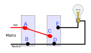
Both switches will still be connected to the (usually white) neutral wire at points (B) and (D), but the (usually black) LINE coming into the first switch will be connected with a wire nut to both the LINE of the switch, and one of the (often red) traveler wires. Note that the LOAD wire in the switch on the left will not be connected to anything – you can just cut it or cap it with a wire nut. The switch on the right will have its LINE wire connected at point C, which is of course the original traveler wire, but is now just a regular LINE wire. Thea LOAD for this switch will be connected at point (E), which actually powers the light.
So if the left switch has no LOAD connected to it, how does it control the light? That isn’t actually done via a physically connection like the original switch, but via a virtual connection using an Insteon scene. In the ISY-994i you create a scene for this light, adding both switches as both the controller and responder. That way, when you click “on” on either switch, the other will respond – and ultimatly it’s the switch on the right that’s actually sending power to your light. Aside from the re-purposing of that traveler wire, this is the same way you’d set up the buttons on a KeypadLinc – none of those physically connect to the device you’re controlling, but they simply send Insteon signals to the switch that does control it.
A final interesting point: we’ve talked about options for Insteon switches, including high wattage, dimming, and dual-band. While you may want both switches to be dual-band to increase the nodes in your mesh network, because the switch on the left does NOT actually power the light, it does NOT need to be high-wattage – or even dimmable for that matter. This can save some significant cash on multi-way circuits by getting cheap switches for all but the one that’s controlling the load.