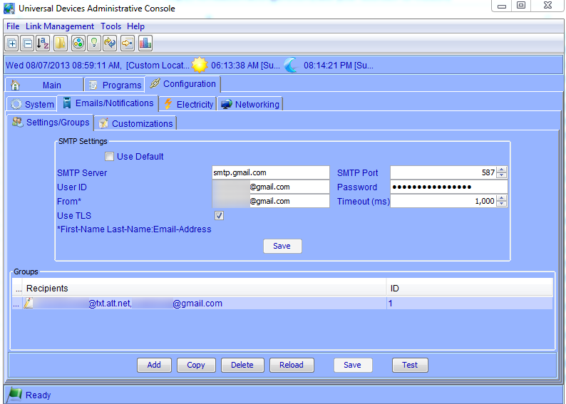
Table-top photo frames based on Android are great and all, and I’ve already covered a wall-mounted frame which is powered through existing low-voltage lines, but I wanted to replace that old photo frame with my new Lenovo Tablet for not just photos but also as another console for my custom Intellihome app. This would give me a secondary location where I could control my home automation system, similar to this setup but without the extra computer powering it.
This posed a couple of challenges: by itself, the tablet would look a bit awkward on the wall, and the existing power connector was a bullet-connector rather than the mini-USB that the tablet provided. I resolved the first problem with some re-purposing of an old frame and 3D printing, and the second with a bit of testing and soldering.
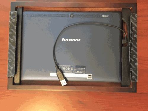
First, the original frame was some ancient Kodak job that I got as a gift, so I’m not even exactly sure it’s available any more to link to. But the wood frame containing the electronics was mercifully easy to remove, and even better was almost a perfect fit for my tablet – just a little too wide. Fortunately, the power switch for the tablet is on the side and I’d need a tiny bit of space to access it and the USB port from the front of the frame, so the extra width was actually very helpful. Using a caliper I measured the exact dimensions of the mounting brackets I’d need, and modeled the parts in the awesome, free AutoDesk 123D Design. Printing out the parts on my FlashForge 3D printer to make room for the power button and short right-angle USB connector, and attaching some velcro to the back, I ended up with this:
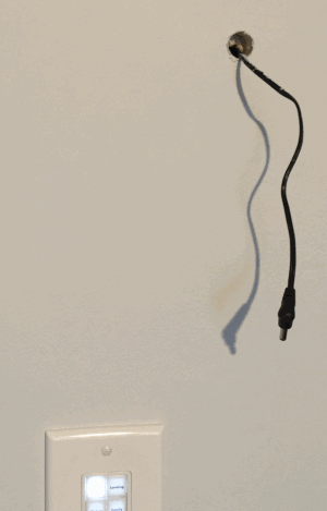
At this point the problem is that, while I have low-voltage power coming to this wall location, it’s a bullet connector at the end and not a USB port:
The solution is pretty simple – in any USB cable, there are several wires. Two of them carry power and the other two carry data – the trick is simply to figure out which is which. Usually the red wire is positive, black is negative, and others are data. But it’s easy enough to confirm this – cut the USB cable, plug it into a computer port (being careful not to short out any wires), and use a multimeter to confirm the voltage (you know you’ve found the power leads when you get about +5V).
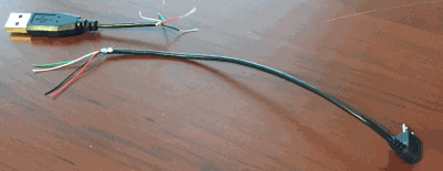
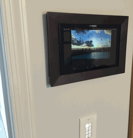
At this point I threw away the USB connector, sniped off the bullet connector from my power wire and attached the “micro” end of cable to the proper red and black wires. Using the velcro to attach the entire unit to the wall, I ended up with a nice, clean touchscreen interface for my home automation system, that also has the benefit of running a slide show when it’s not being used for anything else. Notice the tiny gap on the left side of the tablet that I can use to stick a pen in and toggle the power:
If you’re interested in seeing the source files for the 3D-printed objects I used here, they’re up on Thingiverse!